RD500 Powervalve Joints
Moderator: rztom
-
Captaincosmos
- Posts: 45
- Joined: Sun Nov 01, 2020 11:19 am
- Location: Yorkshire, England
RD500 Powervalve Joints
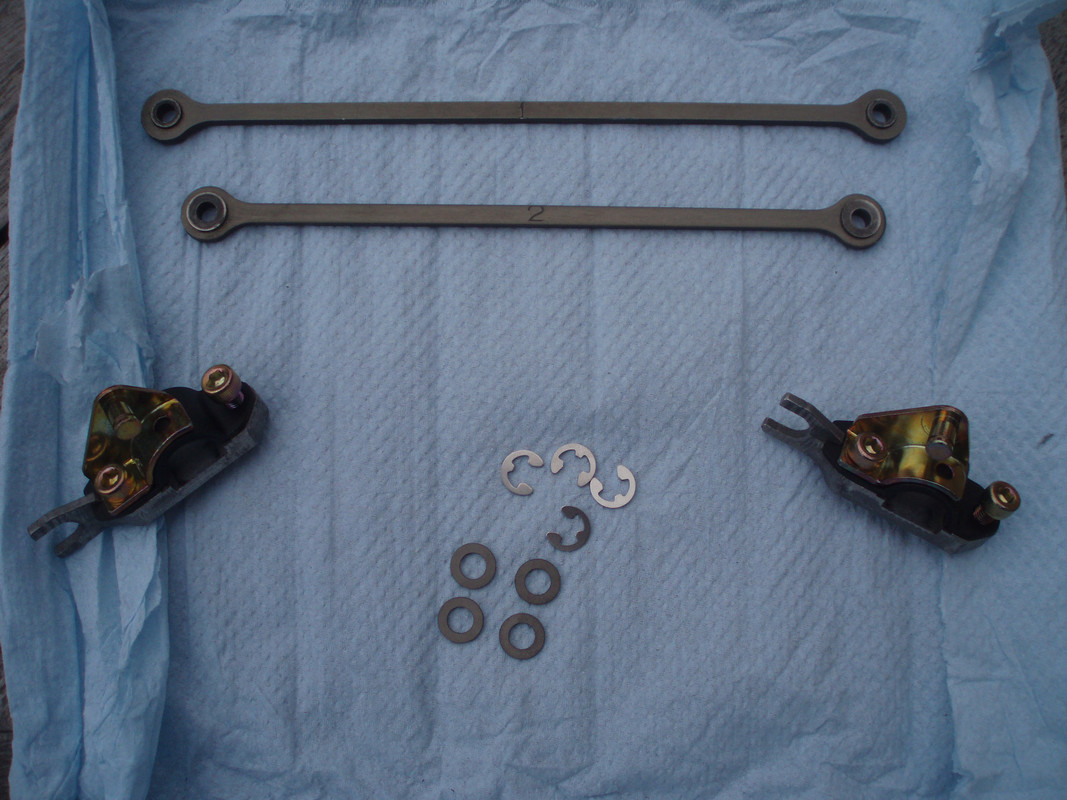
I’m trying to put together a Powervalve pulley mechanism for an engine I’m building. I have bought two valve joints/clamps which came as two pieces each, but have found that they’re missing a third piece that sits on top of the joint, which serves as the connecting point for the control arms. I’m working blind on this because I’ve never seen the mechanism, nor can I find an image on the web, and my book has no reference to the part. Could somebody post a decent image of the joint and also the control arms if possible, as It looks like I’m going to be making some form of replacement.
-
jackson.40

- *****

- Posts: 2328
- Joined: Fri Dec 30, 2005 7:01 pm
- Location: Cambridge,UK
-
Captaincosmos
- Posts: 45
- Joined: Sun Nov 01, 2020 11:19 am
- Location: Yorkshire, England
Re: RD500 Powervalve Joints
Many thanks for the quick response. I’ve noticed that the pieces that bolt to the top of the clamps are offset and the rods are different lengths, nothing about this engine is easy. 

-
jackson.40
- *****
- Posts: 2328
- Joined: Fri Dec 30, 2005 7:01 pm
- Location: Cambridge,UK
Re: RD500 Powervalve Joints
That's why i like it
-
Captaincosmos
- Posts: 45
- Joined: Sun Nov 01, 2020 11:19 am
- Location: Yorkshire, England
Re: RD500 Powervalve Joints
Looking at those rods, I’m thinking along the lines of the gear change rod from something like an R1. I could cut it in the middle, add or remove a piece to get the approximate length and then use the adjusters to dial in the valve openings. This means I won’t need to be as accurate when fabricating the brackets. I should also be able to polish them up for a bit of unseen bling. I’m sure the brackets will be a different story but I’m new to this so my enthusiasm is high.
Last edited by Captaincosmos on Thu Nov 26, 2020 6:56 am, edited 1 time in total.
-
lost1750GTV
- - - - - -

- Posts: 615
- Joined: Thu May 24, 2018 5:22 pm
Re: RD500 Powervalve Joints
Adjustable is a good thing. If memory serves, the original centrifugal powervalve on tz's had such an adjuster.
-
Speed Freak
- - - - - -
- Posts: 931
- Joined: Sun Oct 28, 2012 6:38 pm
- Location: Voitsberg, Austria
Re: RD500 Powervalve Joints
The PV timing is adjustable at the connecting wheel where both rods come together.
It's a 2 piece design and when you loosen the 2 screws you can rotate them against each other.
For the overall timing there is an adjuster in the cables.
Only thing which is not adjustable is the rotation between the 2 cylinders which are next to each other.
My RD350 has a big deviation - one is open, the second one has a 1mm step at the outlet port.
I solved it with an adjustable center piece.
Or more simple solution: You can also grind down the one with a step.
Or another solution: Make them independent and put another 2 cables to the PV motor for the right PV
My bikes:
RD500 YPVS 1GE
RD350 YPVS 31K 1985
Honda CBR 1000 RR SC57
Yamaha R1 RN04
RD500 YPVS 1GE
RD350 YPVS 31K 1985
Honda CBR 1000 RR SC57
Yamaha R1 RN04
-
silverstrom
- - - - - -
- Posts: 3241
- Joined: Sat Feb 04, 2012 7:36 am
Re: RD500 Powervalve Joints
That is what I did with my 350. 4 cables for 2 valves. Left and right valves are completely independent from each other.Speed Freak wrote: ↑Sat Nov 28, 2020 7:45 am
Or another solution: Make them independent and put another 2 cables to the PV motor for the right PV

Re: RD500 Powervalve Joints
Thats what I did on my RD500 - each power valve independantly controlled with 2 separate cables - so 8 cables connected fo the servo motor. Had to machine a new drum of course to connect 8 cables.

Last edited by wolfgangh on Mon Nov 30, 2020 7:03 am, edited 2 times in total.
-
Captaincosmos
- Posts: 45
- Joined: Sun Nov 01, 2020 11:19 am
- Location: Yorkshire, England
Re: RD500 Powervalve Joints
I’m trying to visualise the eight cable set up, how did you connect the eight cables to each of the valves?
Re: RD500 Powervalve Joints
I have added a picture in above post, will try to post more details. Basically each power valve has its own pulley with 2 cables attached to
-
Captaincosmos
- Posts: 45
- Joined: Sun Nov 01, 2020 11:19 am
- Location: Yorkshire, England
Re: RD500 Powervalve Joints
Now I understand. I had visions of you connecting the cables on the right side of the cylinders using the pulley system from a 350 ypvs. For now, I’m going to try the gear change rod approach as the parts are readily available (cheap), the trickier bit will be making the brackets to a reasonable standard with something close to the right offset at the connector pins. Before I can even start making the rods, I need to, source a set of rear cylinders, without them, I won’t be able to estimate the length of the rods.