Electronic tach signal pick up

General forum on troubleshooting electrical problems and modifications to electrical systems

Moderator: rztom

Message
Author
User avatar
kpke
-----
-----
Posts: 2553
Joined: Sun Nov 23, 2008 2:22 pm
Location: Livermore, CA

Electronic tach signal pick up

#1 Post by kpke » Tue Feb 03, 2015 1:33 am

I bought this china tach some time ago for a project bike. It will go on a bike with an 85 USA harness and CDI.

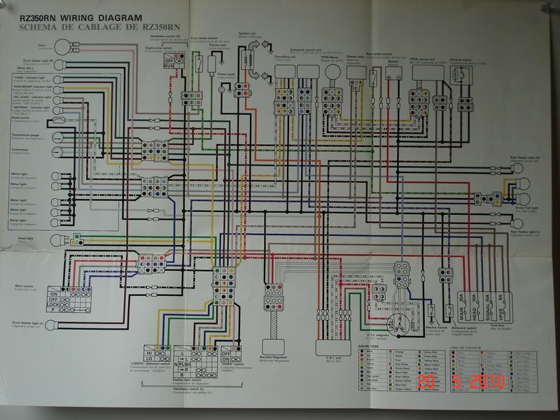
Where can I pick up a tach signal for this thing? :smt017

The instructions are a bit vague of course but it does say for the Blk/Yel wire with function "Rev" should connect to "Magneto". I think it needs to tie in to one of the wires coming off of the CDI, but really don't know.

Maybe someone that has done the R1 conversion can comment as to where they picked up the tach signal??? Or some other electronic tach, trail tech or ???

I think I've got the rest worked out although unsure if the temp sensor will work properly. The KOSO on my 500 required a different sensor.

I will dummy wire it up soon to light it up to verify that it functions at all. Before making a mounting panel.

Thanks!!!

Image

User avatar
JonW
Posts: 10613
Joined: Sat Oct 10, 2009 4:33 am
Location: Sydney
Contact:

Re: Electronic tach signal pick up

#2 Post by JonW » Tue Feb 03, 2015 5:13 am

red white and green white are the pickups, but if you can find the black yellow it will be what you want, it only goes as far as the PV on the early models.

but... be sure the voltage is ok for the new unit. some only sense and dont use the feed, thats what you really want... if so you could even use the white wires and then use the settings on the dash (if it has them, koso does) to divide the pulses. FWIW it was soemthing like 32 for the LC... same electrics really...
80 XT500 Supermoto!
81 RD350LC Resto
82 RD421LC Hybrid
82 RD350LC decapitation project
82 RD250LC JDM '251LC' YPVS
83 RZ350 Resto
84 RZ500 Resto
85 RZ350 F1 Resto
86 RZ350 F2 Resto
86 RZ350 F2 Hybrid

Like Watches? www.PloProf.com & www.DeskDivers.com

User avatar
nikfubar
Posts: 509
Joined: Mon Jan 25, 2010 9:04 pm
Location: Sunny Sussex

Re: Electronic tach signal pick up

#3 Post by nikfubar » Tue Feb 10, 2015 2:05 pm

If your CDI was meant to run an electronic tacho (later YPVS models) this wire will run the Koso tacho , well it did on my R1 set up. On my previous bike I had a Vapor dash & this used the + wire to the coils to run the tacho.
Image

Running on 3

User avatar
kpke
-----
-----
Posts: 2553
Joined: Sun Nov 23, 2008 2:22 pm
Location: Livermore, CA

Re: Electronic tach signal pick up

#4 Post by kpke » Wed Feb 11, 2015 1:35 pm

Thanks for the replies guys!

Jon, I am looking at a 1984 schematic the pickups from the "GENERATOR" are white/red and white/green. Is this what you meant? And one of those wires will give me a tach signal? Those two wires go from the generator directly to the CDI unit.


Also, it sounds like the preferred pickup would be the black/yellow going from the CDI to the YPVS control unit. I will have to verify that the 1985 CDI has this wire. I know there are differences in the CDI wiring from the 1984 to 1985.


nikfubar, this bike did not have an electronic tach. It sounds like another option would be the orange wire from the coil as you did on your "previous bike"???

User avatar
JonW
Posts: 10613
Joined: Sat Oct 10, 2009 4:33 am
Location: Sydney
Contact:

Re: Electronic tach signal pick up

#5 Post by JonW » Wed Feb 11, 2015 7:15 pm

Well... yeah... kind of... I doubt you would blow up a modern unit like this, but dont blame me if you do lol.

the W/G and W/R are the pickup feeds and Smurph used them on his R1 dash. check out that thread for info on that.

I would be tempted to use the B/Y as you say, its the right type of feed.

The orange did not work at all for me with my Koso EGT+Rev/Water.

Do us a pic of the instructions, my Koso stuff was very vague but as it had adjustment in the software it worked out fine.
80 XT500 Supermoto!
81 RD350LC Resto
82 RD421LC Hybrid
82 RD350LC decapitation project
82 RD250LC JDM '251LC' YPVS
83 RZ350 Resto
84 RZ500 Resto
85 RZ350 F1 Resto
86 RZ350 F2 Resto
86 RZ350 F2 Hybrid

Like Watches? www.PloProf.com & www.DeskDivers.com

User avatar
Off Road
-----
-----
Posts: 2077
Joined: Thu Oct 01, 2009 1:31 am
Location: Alberta, Canada

Re: Electronic tach signal pick up

#6 Post by Off Road » Thu Feb 12, 2015 12:23 am

JonW wrote:... I doubt you would blow up a modern unit like this, but dont blame me if you do lol..
What he said. :smt003

From what I've read, not all tachs use the same input signal level.

The Zeel has 2 tach outputs.
The normal one for the RZ electronic tach, is a pretty high voltage signal.
The aux. tach output is a 12v signal.

On the 85 Canadian RZ (with electronic tach), the Grey Tach Wire is connected to the Orange Coil Wire.

Image

User avatar
JonW
Posts: 10613
Joined: Sat Oct 10, 2009 4:33 am
Location: Sydney
Contact:

Re: Electronic tach signal pick up

#7 Post by JonW » Thu Feb 12, 2015 12:38 am

So we have 3 possibles...

O
B/Y
W/G or W/R

Anyone know what the outputs are on those?

People have had issues using the Zeel feed, but they may have had bad dash's anyway... worth asking Borut about what that outputs perhaps if running one? I never have, but will do one day, if anyone knows please do chime in here.
80 XT500 Supermoto!
81 RD350LC Resto
82 RD421LC Hybrid
82 RD350LC decapitation project
82 RD250LC JDM '251LC' YPVS
83 RZ350 Resto
84 RZ500 Resto
85 RZ350 F1 Resto
86 RZ350 F2 Resto
86 RZ350 F2 Hybrid

Like Watches? www.PloProf.com & www.DeskDivers.com

User avatar
steveloomis
-----
-----
Posts: 1507
Joined: Tue Dec 06, 2011 11:18 am
Location: Oklahoma USA

Re: Electronic tach signal pick up

#8 Post by steveloomis » Fri Feb 27, 2015 6:57 pm

The Zeel aux tach output is 1/2 the number of 12volt pulses so tach will read 1/2 the rpm. I use this with a Baker Tach corrector and double the pulses. Tach reads right. The hi voltage output is too much for the R1 tach, however, with a couple of resistors you can reduce it to a usable level. I assisted a guy from Toronto I believe. If you search this site you may find it. He tells which resistors values he used. He may see this post and respond.
'81 RD350LC hybrid w/84 RZ engine. Zeel, Old style Toomeys, Yboot and filter 420 main 22.5 pilot, Air screw 2.5 turns out, DJ needle 2nd from top, Canadian VM26 carbs.
'85 KR/RZ US. Tank is seeping causing a blister in paint.....

User avatar
JonW
Posts: 10613
Joined: Sat Oct 10, 2009 4:33 am
Location: Sydney
Contact:

Re: Electronic tach signal pick up

#9 Post by JonW » Sat Feb 28, 2015 5:00 am

I hope so, it would be good to link that info between these threads...
80 XT500 Supermoto!
81 RD350LC Resto
82 RD421LC Hybrid
82 RD350LC decapitation project
82 RD250LC JDM '251LC' YPVS
83 RZ350 Resto
84 RZ500 Resto
85 RZ350 F1 Resto
86 RZ350 F2 Resto
86 RZ350 F2 Hybrid

Like Watches? www.PloProf.com & www.DeskDivers.com

User avatar
steveloomis
-----
-----
Posts: 1507
Joined: Tue Dec 06, 2011 11:18 am
Location: Oklahoma USA

Re: Electronic tach signal pick up

#10 Post by steveloomis » Sat Feb 28, 2015 1:15 pm

I found Ken, his handle is Joken. I sent a PM so hopefully he will have the resistor network values.

Here is a sketch.


Image

The values of the two resistors is what is needed to make this work.
'81 RD350LC hybrid w/84 RZ engine. Zeel, Old style Toomeys, Yboot and filter 420 main 22.5 pilot, Air screw 2.5 turns out, DJ needle 2nd from top, Canadian VM26 carbs.
'85 KR/RZ US. Tank is seeping causing a blister in paint.....

User avatar
mixalive
Posts: 102
Joined: Tue Sep 07, 2010 11:11 pm
Location: Austin, TX

Re: Electronic tach signal pick up

#11 Post by mixalive » Wed Feb 20, 2019 6:18 pm

To find the resistor values, use Equations: Vo= Vin*R2/(R1+R2) and R2/R1= Vo/(Vin-Vo)
Or use the calculator on this site:
https://www.daycounter.com/Calculators/ ... ator.phtml
RZ350 with FZ600 swingarm, FZR600 wheels, front end and FZR400 bodywork.

bitzz
Posts: 121
Joined: Fri Feb 17, 2012 10:54 pm
Location: Omemee, Canada

Re: Electronic tach signal pick up

#12 Post by bitzz » Wed Feb 20, 2019 8:01 pm

Positive side of the coil?

User avatar
Zedixe13
-----
-----
Posts: 688
Joined: Wed Jan 16, 2008 1:39 am
Location: Quebec city Canada

Re: Electronic tach signal pick up

#13 Post by Zedixe13 » Thu Feb 21, 2019 1:42 am

The tach is driven by the Black /yellow that goes to the CDI and the YPVS unit on the Canadian RZ .

MK
Posts: 822
Joined: Sat Nov 26, 2005 11:44 am
Location: Wolfenbüttel, Germany
Contact:

Re: Electronic tach signal pick up

#14 Post by MK » Thu Feb 21, 2019 11:37 am

The Koso works with the B/Y spliced between CDI and PV Box. It holds the capacitor voltage inside the CDI (around 200V positive rectangle going to zero when firing)
It required the following settings rpm 2C 2P (2 Cylinder , 2 Piston) and impulse to "Hi".

Using the orange cable (spliced between CDI and HT coil) will also hold a kind of inverted signal, a short 200V peak on each ignition event. Some have succeeded in feeding this to aftermarket tachs.

Both first methods have a risk of damage if the tach is not suited and not protect against high voltage.

The w/r w/g signal is very weak (just a peak of a few V), but people also reported this working with their tach.

A method not yet mentioned would be to use a kind of "antenna". Wrap a wire around the HT cable and feed the other end to the tach input. Also a weak signal, but also a common method to get a signal.

The last two would be the first to try, as they're the least dangerous.

If it's a cheap China knock off, it likely works with one of the above, but may lack an adjustment for number of pulses per rotation. In that case it may show the wrong rpm with no way fixing it withva stock CDI.

Aftermarket CDIs like the Ignitech or Zeeltronic do have an additional, configurable tach output (12V square). This is most likely to work on any aftermarket tach.
Bye
Martin

User avatar
mixalive
Posts: 102
Joined: Tue Sep 07, 2010 11:11 pm
Location: Austin, TX

Re: Electronic tach signal pick up

#15 Post by mixalive » Thu Feb 21, 2019 1:22 pm

I'm not sure where the 270V in the above drawing comes from, whether stated or derived. But using 270V with the the voltage divider formula, R1=240K ohm and R2=11K ohm will drop your voltage to 11.8V. I am thinking it may be better to use higher resistance resistors than lower resistance resistors. Whether the 270V is a stated or assumed voltage, it would be best to verify with an oscilloscope before making the final calculations. I say to use an oscilloscope because a multi-meter would probably read an inconsistent reading of a voltage pulse. https://www.daycounter.com/Calculators/ ... ator.phtml
Image
RZ350 with FZ600 swingarm, FZR600 wheels, front end and FZR400 bodywork.

Post Reply